
TESTING STARDRIVE PROPULSION
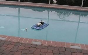
StarDrive was first tested in a computer running the Computer Assisted Design and testing software (Solid Works and Cosmos Motion). When that test confirmed that the concepts embodied in the invention worked, a physical test model was created by the 3D printing “rapid prototyping” process that literally “prints out” a working model directly from the computer’s test data. That test model, shown below, passed two successive tests, demonstrating that the computer was right. Here is a picture of the first test performed in a low friction test facility.
To further confirm that the StarDrive Propulsion system was converting the angular momentum of the thrust masses into the linear momentum of the test device shown, a load cell test platform was designed and constructed using 4 load cells mounted at right angles to each other that measure the amount of pull each load cell receives. Those load cells are channeled through small sensor boards that allow each channel to be balance against all of the others before and after each test run so the actual amount of thrust generated by the test device can be plotted against the 3 other channels. Those sensor boards feed into a fast Fourier analysis board connected to a lap top computer where the results are displayed and stored. Here is a picture of that test bed.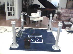
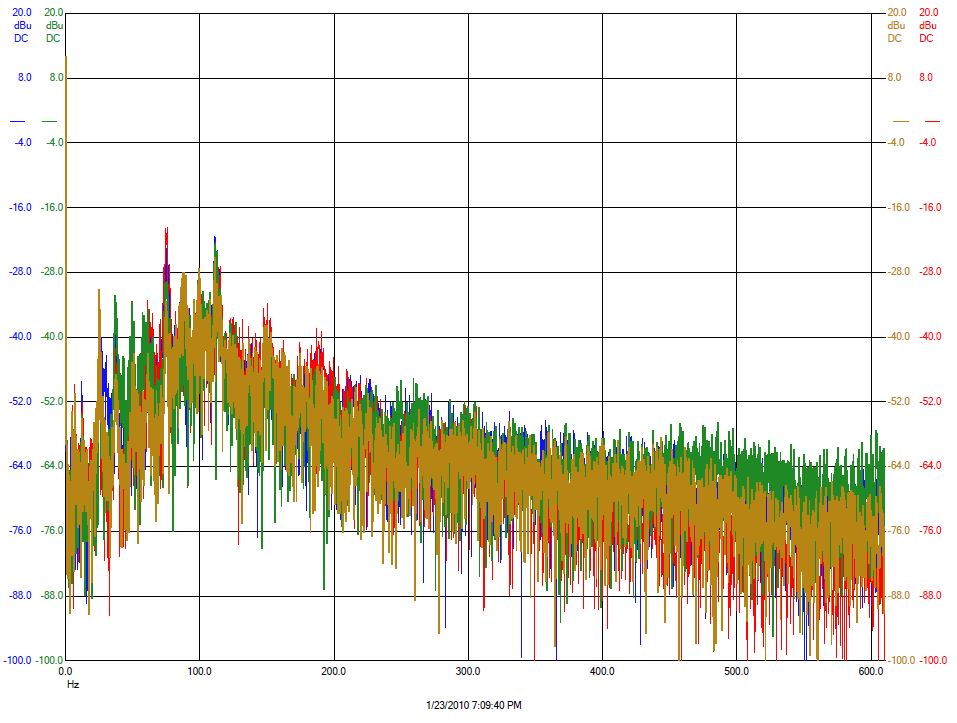
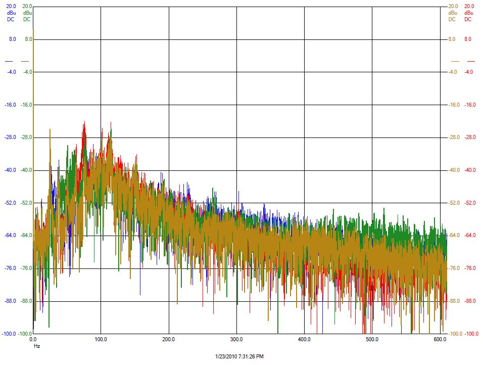
Here is the graphic output of one of those tests. The red channel is measuring the predicted thrust output, the gold channel is the opposite end channel or anti thrust position. Blue and green are the side channels. The peak at around 78 Hertz measures the thrust.
Load Test 3: Silicone Ramp
Load Test 4: Polyurethane Ramp